
ComNav Technology · Case Study
Project Overview
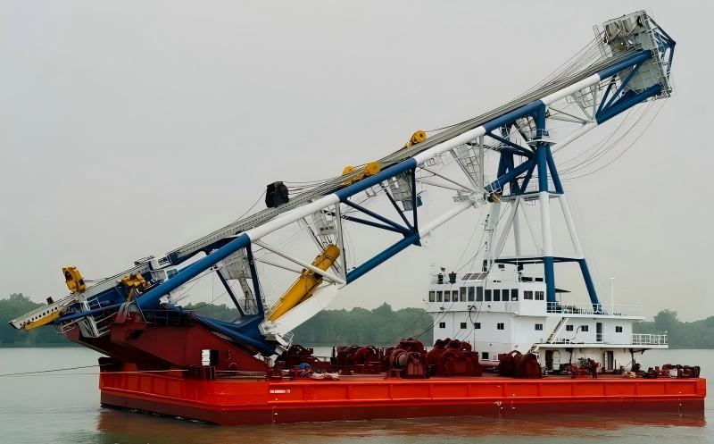
The MASINDRA 72 is a 72-meter steel piling vessel operating at a port in Malaysia. It is primarily deployed for piling works of offshore terminals and near-shore marine structures.
Conventional piling operations rely on manual stakeout and operator experience, whose accuracy is susceptible to ocean waves and sea winds. When performing complex raked pile installation, this method results in time-consuming vessel positioning and a high re-driving rate of foundation piles, thus lowering operational efficiency (Fig. 1)..
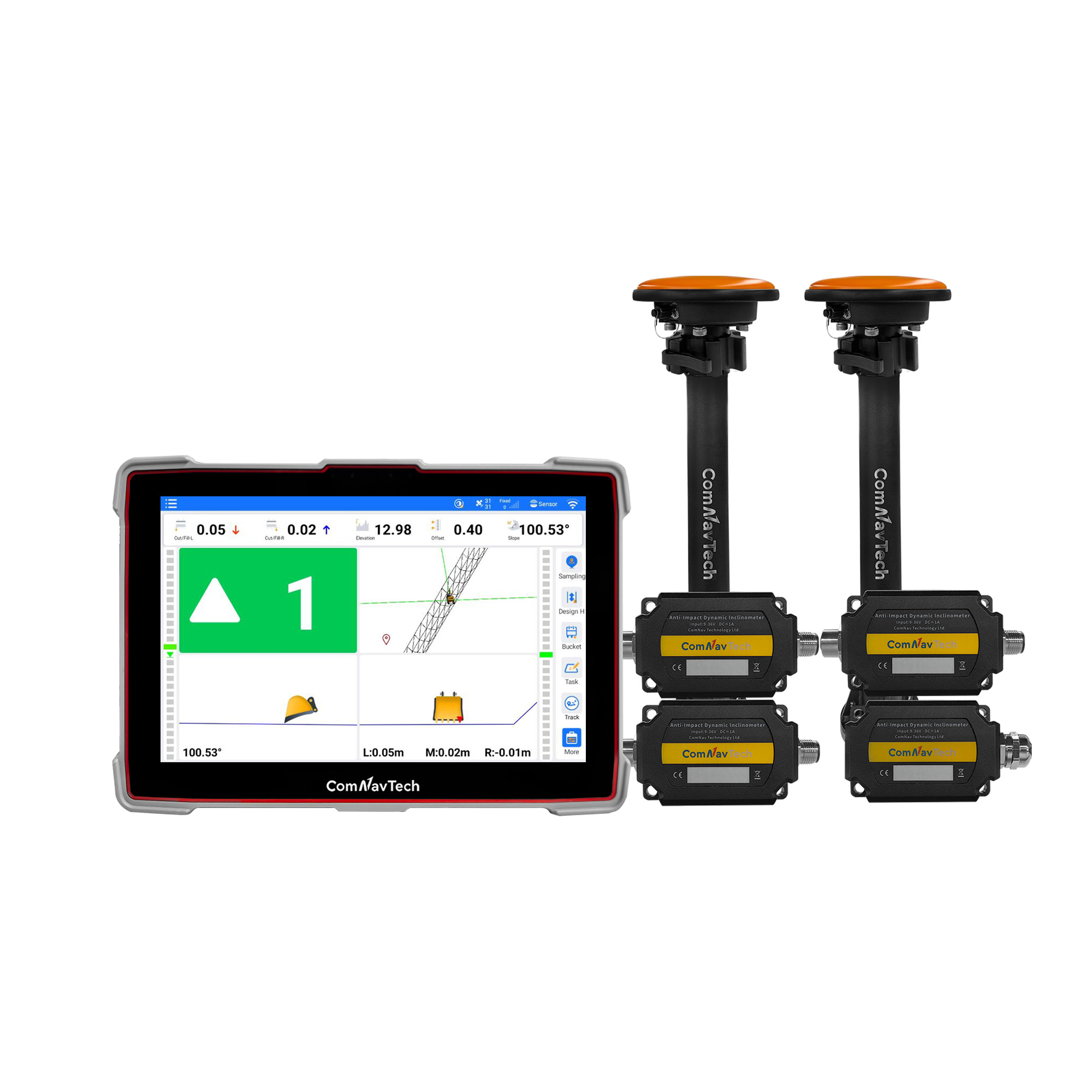
The project utilized the XP300 piling guidance system to complete the installation, commissioning, and accuracy verification of the equipment on the MASINDRA 72 piling vessel. Based on high-precision GNSS positioning, IMU technology, and ComNav's proprietary algorithms, the system enables precise vessel positioning and real-time monitoring of pile location and orientation throughout operations, meeting multi-angle piling requirements.
Given that the operation areas are mostly offshore regions without public network coverage, a local area network was established using outdoor wireless AP to allow the bow command personnel to monitor operational processes and progress in real time via screen sharing on tablets . This significantly shortened the on-site operation cycle, reduced labor costs, and provided a high-precision, highly efficient digital solution for offshore pile foundation construction.
Challenges and Solutions
Challenges
- Limited precision: The piling vessel frequently pitches and rolls under waves and wind, making it difficult to manually stabilize the pile tip at the target position.
- Environmental constraints: Conventional total station pile positioning requires good line of sight and is often affected by the pile frame, weather, and sea state.
- Engineering complexity: Raked pile installation requires simultaneous control of the pile-top position, vessel heading, and pile-frame rake angle. Traditional methods cannot provide real-time visibility into these parameters.
- Difficulty in multi-person coordination: Communication between bow supervisors and piling vessel operators can be time-consuming and error-prone, restricting operations mostly to daytime hours.
XP300 Solution
- GNSS + IMU positioning: Provides real-time vessel and pile-frame positioning without optical line of sight.
- Real-time raked pile guidance: Simultaneously guides pile position, heading, elevation, and pile-frame pitch.
- Wireless remote monitoring: Enables bow control personnel to monitor the same guidance information through tablets via an outdoor wireless AP.
- Automatic pile records: Automatically records pre-driving and post-driving coordinates and attitude data for traceability.
Project Summary
Instruments
| Instrument | Quantity |
|---|---|
| XP300 Piling Guidance System | 1 |
| Outdoor Wireless AP | 1 |
| Base Station | 1 |
Software
- XPiling
- Survey Master
Project Procedure
1. Set up Base Station
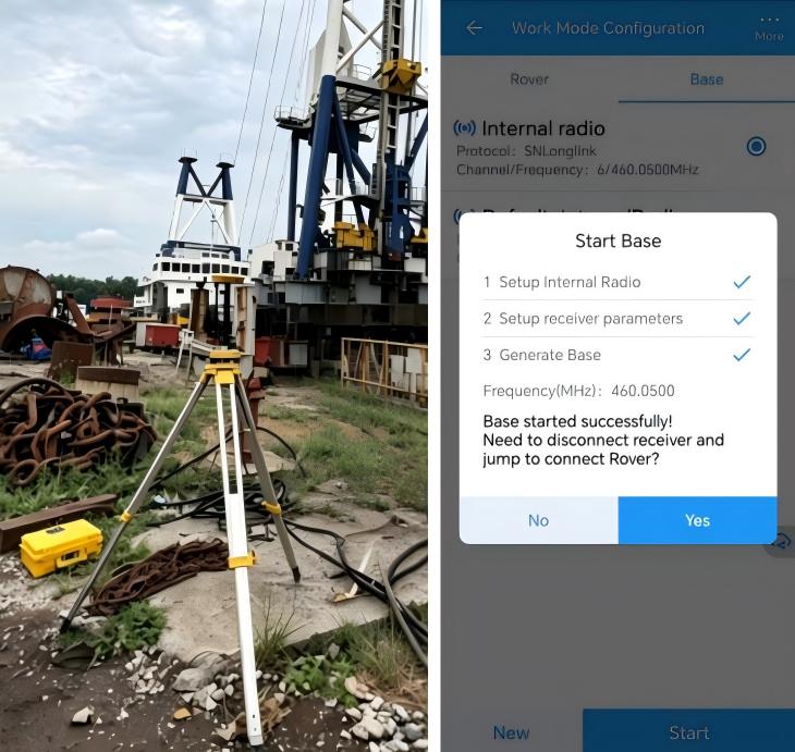
An N2 receiver is set up as a base station at a control point, configured with the SNlonglink radio protocol to broadcast RTK differential data to the piling vessel tablet(Fig. 2). The N2 receiver integrates a large-capacity battery and a high- performance transceiver radio, ready for immediate use upon setup and power-on, providing a continuous, stable, long-range differential data link for offshore pile driving operations.
2. Equipment Installation
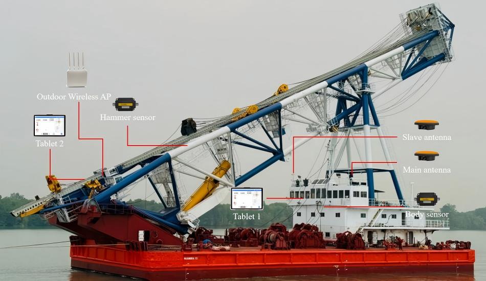
Prior to installation, our project team conducted on-site discussions with the vessel crew regarding the mounting positions of the GNSS antennas and sensors, cable routing, and operational procedures. The two GNSS antennas are mounted on top of the wheelhouse; the body sensor and Tablet 1 are installed inside the wheelhouse; Tablet 2 and the AP unit are installed in the bow control room; and the hammer sensor is mounted on the left side of the pile frame (Fig. 3).
3. Measurement and Calibration
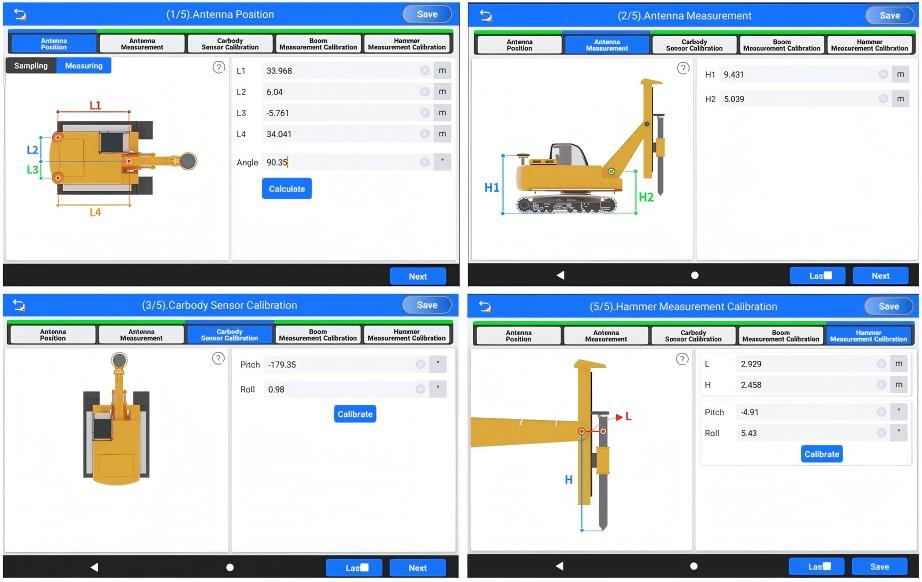
Prior to modeling, a total station is used to survey the main antenna, slave antenna, pile frame axis, and hammer center; the modeling parameters are then derived from the measured coordinates. Key parameters include the horizontal distances from the main antenna to the pile frame pivot (L1) and to the vessel center line (L2) (Fig. 4). The pitch and roll of the body sensor and hammer sensor are also calibrated.
Calibration sequence: Antenna Position → Antenna Measurement → Body Sensor Calibration → Hammer Measurement Calibration.
4. Elevation Guidance Setup
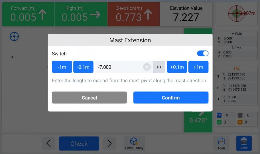
To achieve real-time comparison between the target pile point elevation and the elevation of the bottom marking point of the pile frame mast during the construction process, the mast extension function can be used. Measure marking point with a total station and enter the calculated mast extension value into the software(Fig. 5). The reference position can be changed later as needed.
5. Guidance Operation
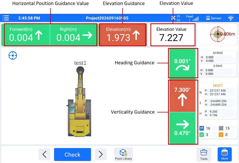
During operation, the main interface displays real-time deviations between the current pile position and the target pile position: forward/backward, left/right, elevation guidance and elevation value, along with heading and hammer verticality guidance value. And the verticality guidance includes longitudinal raked angle guidance and transverse raked angle guidance(Fig. 6).
The operator maneuvers the vessel and adjusts the pile-frame attitude until all deviations fall within tolerance and the pile-frame pitch reaches the target value. Pile driving can then begin.
Accuracy Verification
To verify positioning accuracy, four target pile positions were selected within the work area. The vessel was navigated to each target position, and the piling results were exported from the software point library. The deviations at all four points were within the project's acceptable limits. The results are summarized below.
| Test Pile Point | Target Pile Point (m) | End Pile Driving Coordinates (m) | Error (m) | Heading (°) | Longitudinal Rake Angle (°) | Transverse Rake Angle (°) | |||
|---|---|---|---|---|---|---|---|---|---|
| N | E | N | E | ΔN | ΔE | ||||
| P1 | 221237.50 | -244489.21 | 221237.454 | -244489.172 | 0.046 | 0.038 | 25 | 5 | 0.214 |
| P2 | 221240.22 | -244499.11 | 221240.249 | -244499.071 | 0.029 | 0.039 | 10 | 10 | 0.151 |
| P3 | 221229.84 | -244481.25 | 221229.792 | -244481.240 | 0.048 | 0.010 | 30 | 10 | 0.125 |
| P4 | 221233.69 | -244475.25 | 221233.623 | -244475.227 | 0.067 | 0.023 | 45 | 15 | 0.165 |
Conclusion
This project successfully completed the on-site installation of the XP300 piling guidance system on the MASINDRA 72 piling vessel. The system employs GNSS and IMU integrated positioning, delivering centimeter-level accuracy under complex sea conditions, real-time pile attitude monitoring, and multi-angle piling capability, effectively addressing challenges posed by waves, wind, and visibility obstruction.
The system is designed for straightforward operation and automatic data logging, helping improve piling accuracy and work efficiency. The successful deployment demonstrates the applicability of this guidance system to overseas port piling projects and provides a digital solution for similar offshore piling operations.
Looking for a Piling Guidance Solution?
Contact ComNav Technology to learn more about the XP300 Piling Guidance System.
Learn More About XP300